Relais schalten smarthometricks.de
The ESP8266 runs on 3.3V power and logic, and unless otherwise specified, GPIO pins are not 5V safe! The analog pin is also 1.0V max! ©Adafruit Industries Page 10 of 73. I2C & SPI pins You can use the ESP8266 to control I2C and SPI devices, sensors, outputs, etc. While
FichierESP8266 RelaisSchema.PNG — GCE Electronics
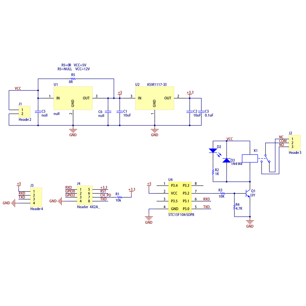
The circuit above have an AMS1117 IC and two capacitors. handles for receiving the input voltage of +5V and regulating it to a voltage level of +3V3. The figure 7 shows the IC on the printed circuit board. Figure 7 - +3V3 Voltage Regulator Integrated Circuit. Now, we will introduce the ESP8266 CHIP circuit block.
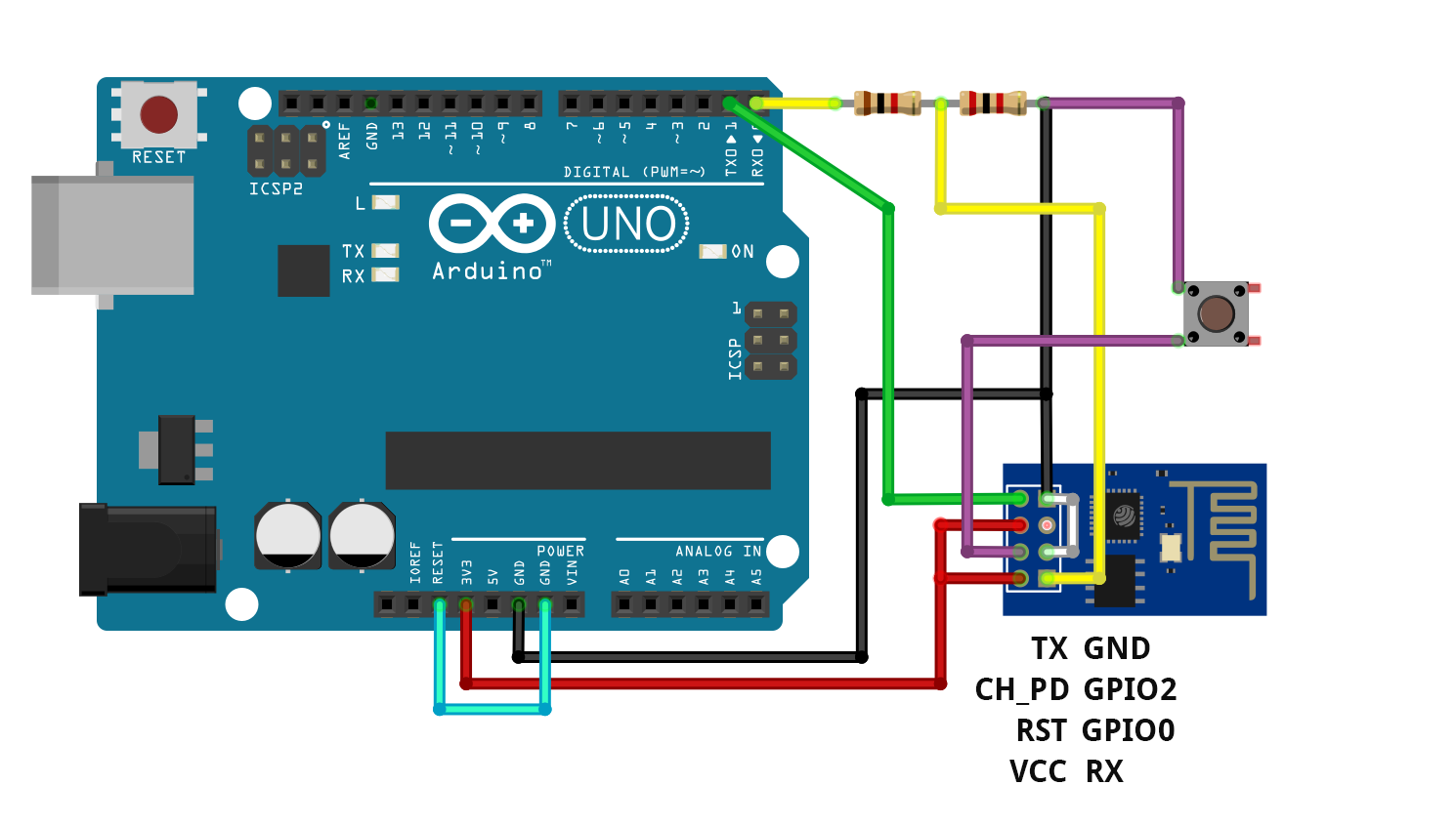
Arduino Esp8266 PostDaten auf Website / Schritt 2 Schaltplan
The most intelligent device. We developed Shelly 1 with an integrated WEB interface for device management and a secure OTA update. You can set your weekly schedules for On/Off without the need of any additional equipment. Shelly 1 knows your location, gives you high security and provides device access control.
Relay Tutorial for Arduino, ESP8266 and ESP32
Twenty-five percent of the fund is distributed to the Nevada Housing Division to assist low-income households implement energy conservation, energy eficiency and weatherization programs. This fee for electric customers is $0.00039 per kilowatt hours used and $0.0033 per therm of natural gas used.
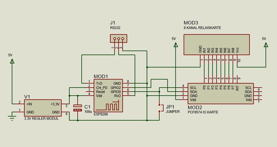
8 Kanal I2C Relais per WLAN ( WiFi ) steuern mit ESP8266 Webserver über Netzwerk
Project Schematic Diagram The circuit diagram for the project "Control a Relay using ESP8266" is shown in the image below. You can see that I've used a single channel relay module in the circuit diagram. Components Required ESP8266 Arduino UNO Resistors (1KΩ and 2.2KΩ) - both are ¼ Watt Resistors Jumper Wires Relay Module Small 5V Bulb Push Button

ESP32/ESP8266 Relay Module Web Server using Arduino IDE Random Nerd Tutorials
noiasca May 25, 2021, 10:47am 2 mindestens diese Punkte fehlen: mach einen groben Schaltplan auf Papier, fotografieren, hier hochladen. Echtbilder vom Aufbau machen, hier hochladen, damit wir überprüfen können ob deine theoretische Verkabelung in Echt stimmt.
ESP8266 ESP01 Modul • Wolles Elektronikkiste
the example of \ESP8266_NONOS_SDK\examples\at\user\user_main.c, ways are delivered on how to implement a self-defined AT Command, " AT+TEST". The structure, at_funcationType, is used to define four types of a command, e.g. "AT+TEST". Copy all files in folder "at" to folder "app" in ESP8266_NONOS_SDK if users need to compile AT.
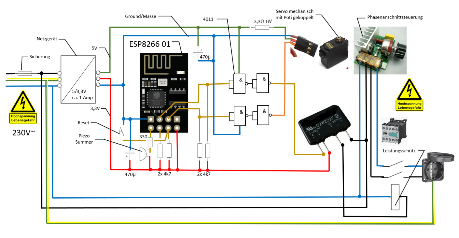
PumpControl mit ESP8266 01 91301 Kersbach
In unserem eBook für den ESP8266-01 mit Relais haben wir euch erklärt, wie ihr mit den AT befehlen und einem Serial Terminal Programm das Relais schalten könnt. Heute möchten wir euch hier zeigen, wie das mit einer Website funktioniert. Am Ende haben wir 2 Buttons mit Ein und Aus. Legen wir los:
liberté Lait innovation esp8266 relais schaltplan écouteur renflement Frugal
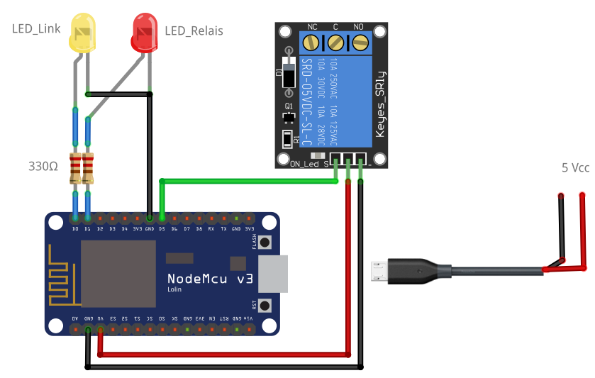
Mit dem Relais können wir über unseren Steuerstromkreis am ESP8266 einen weiteren Stromkreis schalten. Wie immer im ersten Schritt die Liste der verwendeten Materialien: AZDelivery NodeMCU Lolin V3 Module ESP8266 ESP-12F WiFi WiFi Development Board mit CH340 kompatibel mit Arduino inklusive E-Book! Preis: 7,99 €
Tuto Esp8266 Relais
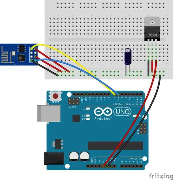
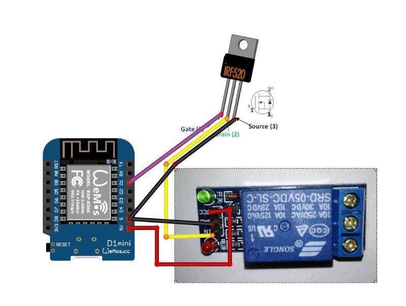
Step 1: Materials ESP8266 WiFi module Arduino Pro Mini 8Mhz, 3.3V 5V Relay module NPN transistor 2N2222 resistor 5K1 AMS1117 3.3V regulator 1000uF capacitor EasyIoT server ( Raspberry Pi or Windows machine) WiFi network (WiFi router) Buying guide for materials: http://iot-playground.com/blog/2-uncategorised/16-esp8266-wifi-relay-switch

Relais beschalten
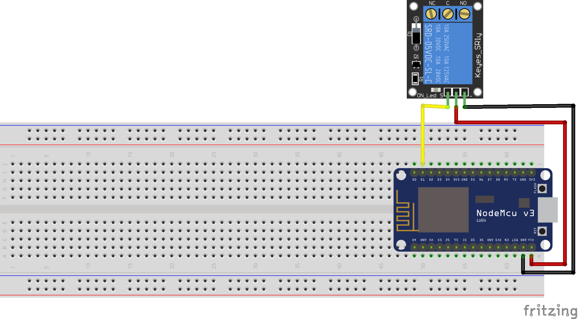
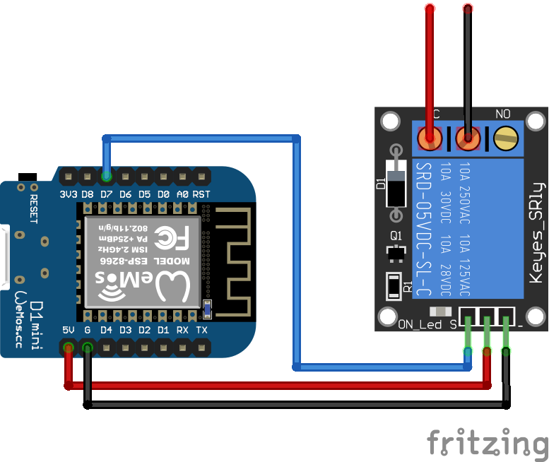
When we use an ESP8266 or ESP32 microcontroller with an operation voltage of 3.3V, we have to use the VIN or 5V output from the USB connection as power supply for the relay module and power the ESP8266 or ESP32 board via USB. The following picture shows the wiring between the most used Arduino, ESP8266 and ESP32 microcontroller and a relay module.
liberté Lait innovation esp8266 relais schaltplan écouteur renflement Frugal
Control Relay with ESP8266 01 Module This project shows how to control a relay with ESP8266. Intermediate Protip 30 minutes 11,071 Things used in this project Story Ideation There are many such videos out there on YouTube, but most of the people have used Relay modules instead of only a relay. Do you know the reason why?

ESP826601S mit Relais bei azdelivery.de AZDelivery
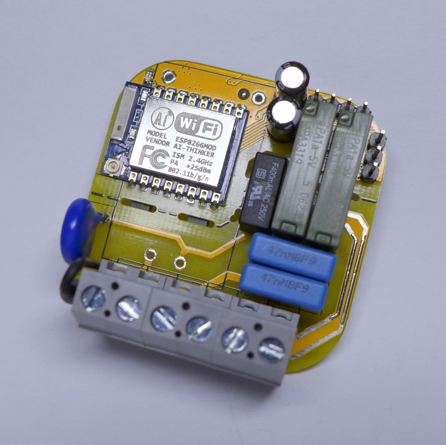
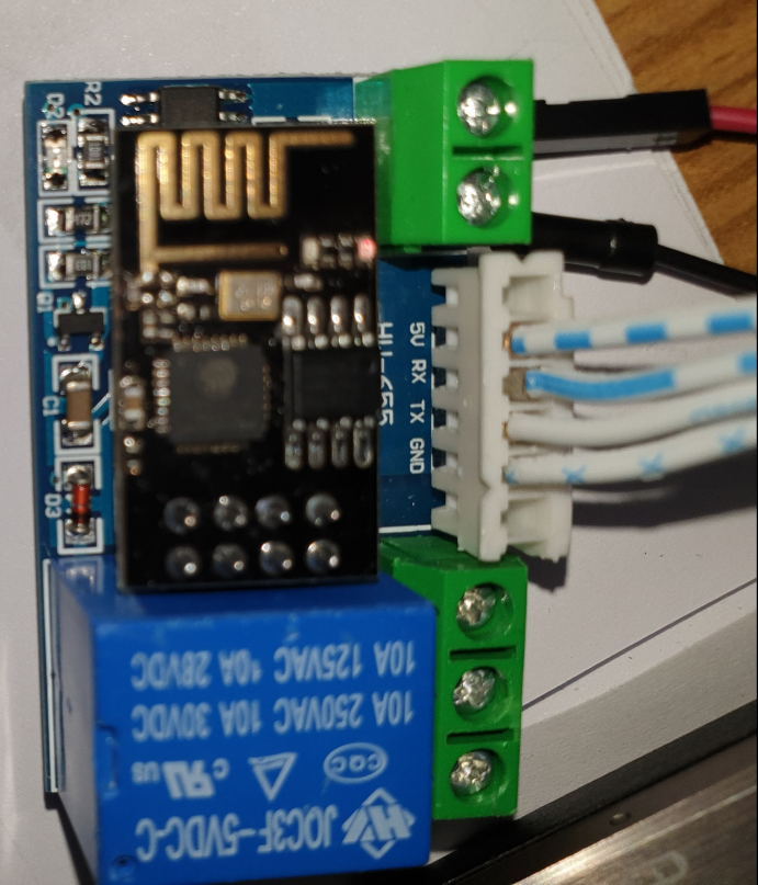
Description This WiFi relay based on AI-Thinker ESP-01/ 01S WiFi module, we use the GPIO0 of ESP-01/ 01S to control the relay by low level. It's easy to DIY your smart switch to any device by your phone anywhere with this smart relay. Specifications Working voltage: DC 5V-12V Working current: ≥250mA Communication: ESP01 or ESP 01S
Esp826601 sur relais HW655 Arduino
In Serial Monitor check if ESP module connects to AP. If connection is successful you will also see IP address of ESP8266. Remember this IP address. Connection. Connect ESP8266 GPIO2 pin to 5V relay module IN. Because relay module operats on 5V and ESP8266 operate on 3.3V we will use 2N2222 NPN transistor to shift levels. Grund is common for 5v.
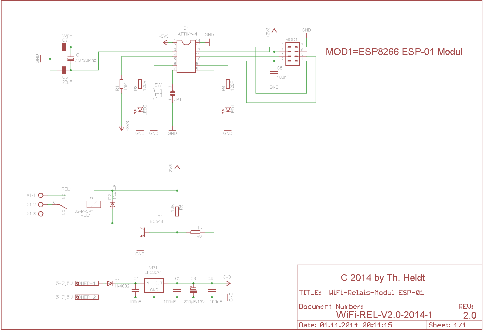
WiFi Relais mit ESP8266 ESP01 Modul
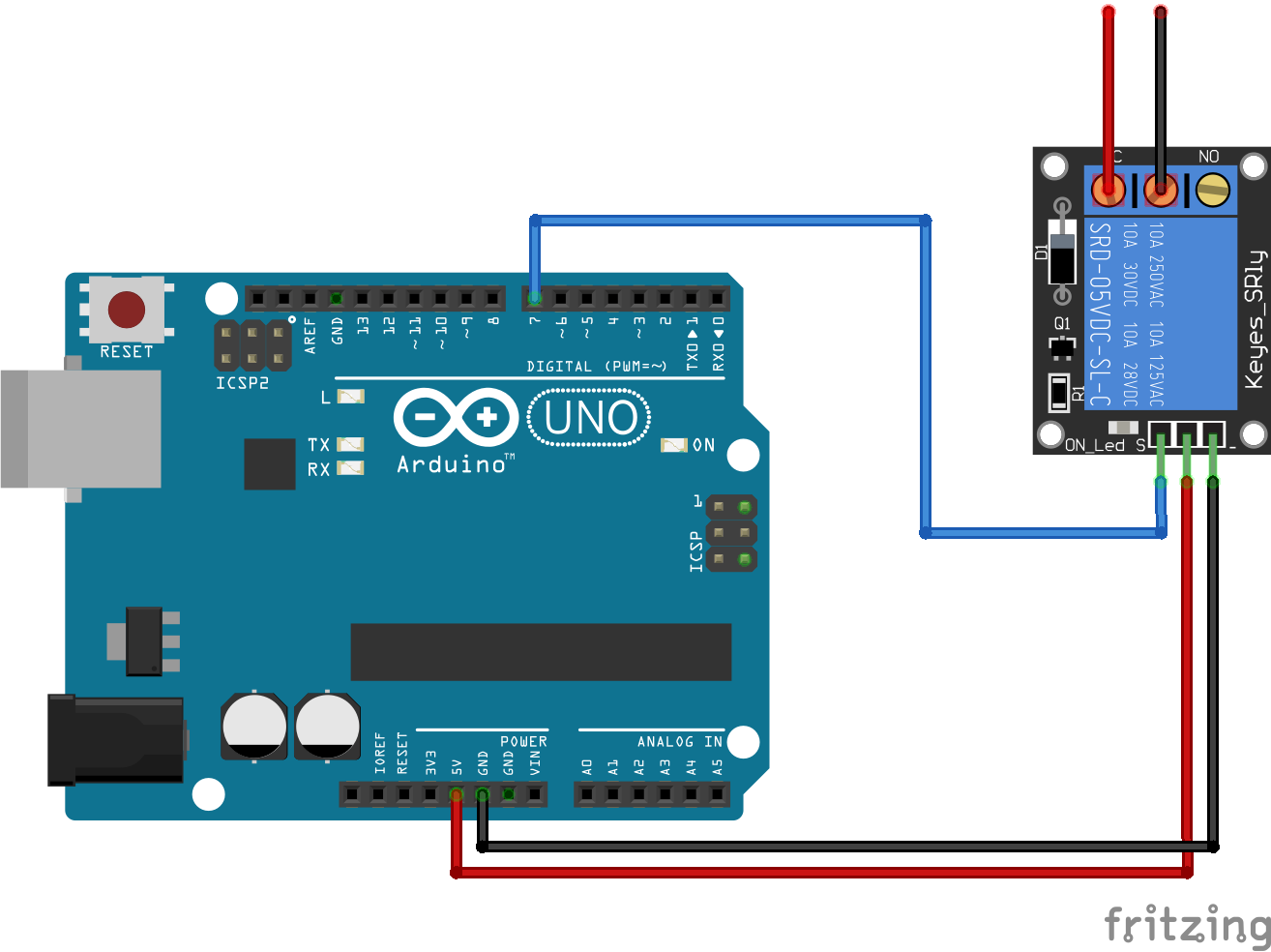
The objective of this post is to explain how to use the ESP8266 to control a relay. Since we are going to control the relay with a digital pin of the ESP8266, we need to use a device that can operate with 3.3V. Fortunately, eBay offers a wide variety of relays suitable to be controlled by a microcontroller, as can be seen here.
ESP826601 mit Relais AT Firmware und eigene NCX Maker Blog
Using a relay with the ESP8266 is a great way to control AC household appliances remotely. This tutorial explains how to control a relay module with the ESP8266 NodeMCU. We'll take a look at how a relay module works, how to connect the relay to the ESP8266 and build a web server to control a relay remotely (or as many relays as you want).